Modeling camera sensors
I have made a simple model of two camera image sensor types.
The first is full color sensor which captures full color at pixel site. Its main and only parameter is fill factor which determines how much space actual sensor covers. This is a simple model of what I know about Foveon sensor in Sigma cameras, but note that the real sensor is much more complex so real results will be different.
The second is classic Bayer color filter array sensor. This sensor captures color too, but in different way. Each sensor element is sensitive only to luminance which would make nice grayscale picture. To make the sensor element see the color, there is a color filter in front of each sensor element. There are three filters types: for red, for green and for blue (which is simplification since filter cannot be described by single passing color, but by response function). The filters for the three colors are alternating in the sensor element grid in Bayer pattern which has odd rows repeating of: blue, green; and even rows repeating of green, red. Blending of color from different places works nicely for flat areas in the picture, but in presence of sharp edges there will be errors. To mitigate these errors the sharp edges have to be blured before light hits the color filters. This is done by Anti-aliasing (AA) filter. If the filter is strong enough there will be no color errors but image will be blured. If the filter is weak or it is missing, the colors on edges will be wrong but sharp. Color errors are also affected by image processor which may add some assumptions like that black-white edges are more common than black-"tiny red/green/blue"-white edge so when it sees the later it will render it as former. Color errors may be amplified by noise (photon noise or readout noise). My model has configurable AA filter size and strongness. The size defines how far from center of the sensor element the color is seen. Strongness is true or false. The true means that AA filter size area is seen by subpixel uniformly. The false means that AA filter size area is center weighted. Pictures below use always strong filter and the filter size is either 2.0 or 1.0 (which means no filter). Interpolation of colors to places where they were not seen is done by averaging nearest colors from same color filter. Sensor like this is used in most of current camera sensors, but image processing here is the simplest I could do, camera makers know how to make it better.
Modeling software
I have made the model in Processing 1.0 scripting language. The Processing is a cool tool for scripting images, animation and interaction. You can download the Processing 1.0 from http://processing.org/. I use it on Linux, but you can use it on Windows or Mac too. The source for my model is available under MIT license here. To use it, paste the script in the code pane. Save with "File->Save as" so that you know the directory where to place input file. Click Run icon and it will read input.jpg from current directory and display it. The input.jpg file is assumed to have dimensions 400x400. Running the script will draw models of both sensor types. Mouse position affects the grid alignment. There are some constants in the beginning of the file you may want to play with.
Comparison on several source pictures
Comparison is done on three pictures for two models with two different settings. The sensor element areas are 81 (CFA) and 256 (Full color) pixels of input image. This corresponds to relative densities of full color 4.7 megapixels (like Sigma SD14 or DP1) and 14.8 megapixel CFA.
Sample 1
The input image is here: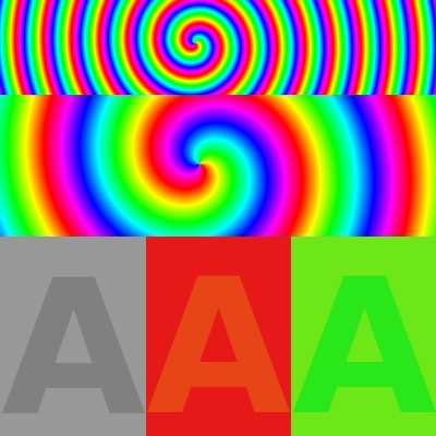
This
image was created to show how both sensor types handle colored
edges. The top part shows high frequency color changes. Middle
part show low frequency color changes. The bottom part shows
low contrast color changes.
Results are here:
Full color fill factor 64%, CFA AA Filter on.
Full color fill factor 100%, CFA AA Filter off.
Mouse over the image to see the second image:
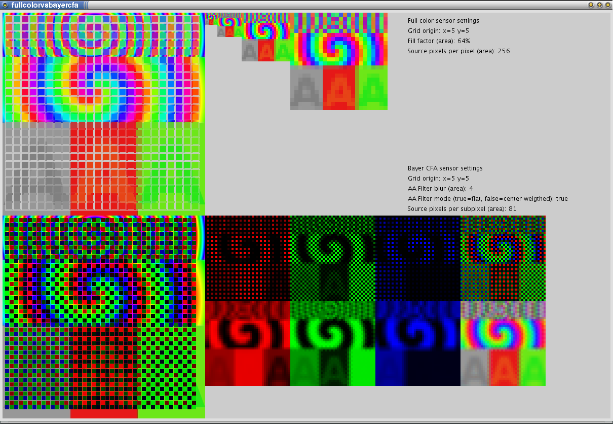
You can see that fill factor on full color sensor affects contrast in case of high frequency color changes. Higher fill factor cause colors to be more average and therefore less contrast. Removing AA Filter in CFA makes the micro-contrast better but color errors may appear (this is more visible in samples 2 and 3).
Sample 2
The input image is here:
This
image is a crop of bridge image taken from DPReview
discussion about color profiles of Foveon SD14 and Canon 50d cameras. This one is from 50d.
Results are here:
Full color fill factor 64%, CFA AA Filter on.
Full color fill factor 100%, CFA AA Filter off.
Mouse over the image to see the second image:

Sample 3
The input image is here: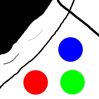
This
image was created to see how models response to black and
white edges and primary colors.
Results are here:
Full color fill factor 64%, CFA AA Filter on.
Full color fill factor 100%, CFA AA Filter off.
Mouse over the image to see the second image:

Sample 4
The input image is here: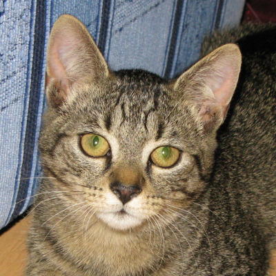
The image is about 30% downsampled crop of my GF brother's cat, captured by Canon G9 camera.
Results are here:
Full color fill factor 64%, CFA AA Filter on.
Full color fill factor 100%, CFA AA Filter off.
Full color fill factor 36%.
Mouse over the image to see the second image:
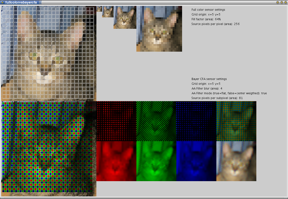
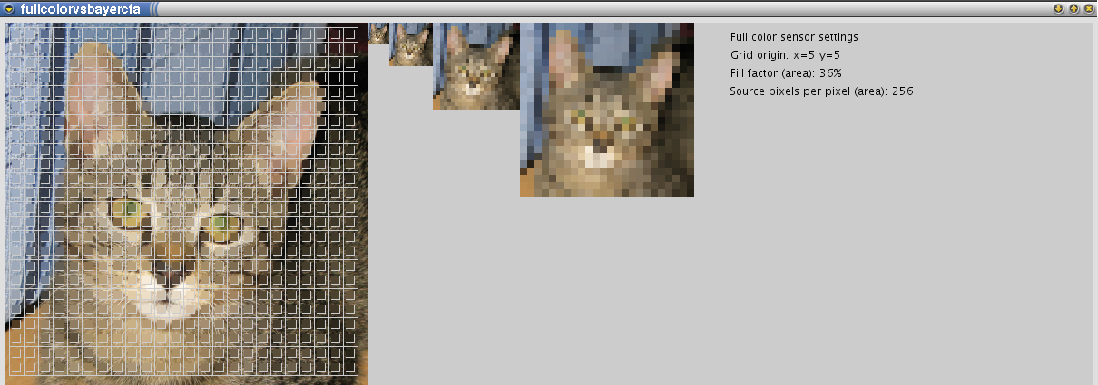
Another image but I made an extra run for full color fill factor of 36% to see how micro-contrast would increased. It looks better for me. However low fill factor may cause aliasing in images with patterns and also it makes sensor less sensitive to light. In case of CFA sensors the small fill factor will just reduce effect of AA filter creating color errors as it can be seen in the second image in this sample.
Last words
So I hope you liked the simulation. You can change the model and play with it if not :-) There are surely much better algorithms to reconstruct the image from CFA pixels. Write me an email if you make some interesting improvements or discoveries with model code. Also there is more to photography than pixel peeping ...
Back to index - Jakub Trávník's resources.